 |
| Rangkaian Comparator Tegangan Sederhana |
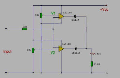
This is a Voltage Comparator circuit can be uses indicates the input voltage differs from two defined limits, V1 and V2.
One application here is to monitor a 12V car battery. V1 can be set to 14V and V2 to 11V thus giving an indication of more than the cost or weak batteries. Op-amp used here is the CA3140 MOSFET. They are used to
advantage because they have less output offset voltage and can switch to 0volts close. If any other use op-amps like the LF351 or CA741 will need to have an offset null control. This is just a 10k preset reached between pins 1 and 5, the wiper connected to the negative supply op-amps or 4 pins. The following is a schematic drawing:
IC CA3140 Description
The CA3140 is integrated circuit operational amplifiers that combine the advantages of high voltage PMOS transistors with high voltage bipolar transistors on a single monolithic chip.

Absolute Maximum Ratings
DC Supply Voltage (Between V+ and V- Terminals) . . . . . . . . . 36V
Differential Mode Input Voltage . . . . . . . . . . . . . . . . . . . . . . . . . . 8V
DC Input Voltage . . . . . . . . . . . . . . . . . . . . . (V+ +8V) To (V- -0.5V)
Input Terminal Current. . . . . . . . . . . . . . . . . . . . . . . . . . . . . . . . 1mA
Output Short Circuit Duration∞ (Note 2) . . . . . . . . . . . . . . Indefinite
Temperature Range. . . . . . . . . . . . . . . . . . . . . . . . . -55oC to 125oC
Maximum Junction Temperature (Plastic Package) . . . . . . . 150oC
Maximum Storage Temperature Range . . . . . . . . . -65oC to 150oC
Maximum Lead Temperature (Soldering 10s) . . . . . . . . . . . . 300oC


0 komentar: